I see this as an A4 or A5 board with the following features.
- A row of 8 toggle switches, each with a corresponding LED and a label to show its position and value in a byte, e.g. bit 3 has a value of 8. The LED is lit for the bits that are set.
- A two-digit LED display showing the value of each half byte as a hex digit, and some text explaining how its derived from binary.
- A three digit LED display showing the decimal value.
- The hex and decimal displays would update as the switches are toggled.
- A push button to trigger sending the byte to a microcontroller which displays it on a small LCD.
- A reset button to clear the LCD.
Kids can then look up the values of the ASCII characters they want, set up the toggle switches to choose the correct value and push the button to write short messages character by character until the reset button clears it all.
Optionally, we could add the ability to send the message to a printer, teletype, web page, twitter etc.
Driving the Displays[]
- The five 7-segment LED digits will be multiplexed for display using 5 output pins to control which 7-segment display is enable at any one time. Two 4011 quad 2-input NAND gates will be used as buffers with the inputs tied together to make them into inverters (I happen to have a couple lying around). A PICAXE pin will be connected to each NAND and used to switch on the corresponding 7-segment display.
- The data for each digit will be output on 7 pins of the 20M2 with each pin powering the same segment of every digit, e.g. pin 1 will be connected to all segment 'a's, pin 2 to all segment 'b's etc.
- The LCD module will be controlled using a serial pin from the main 20M2 PICAXE.
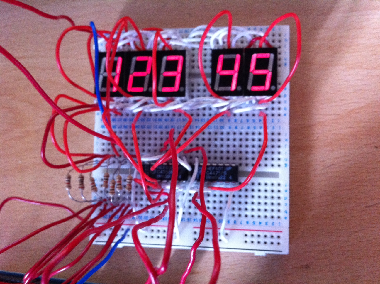
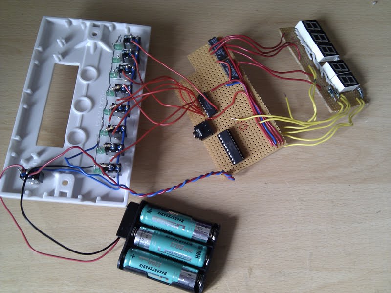
I used a prototyping board to prove the concept with an arduino as I don't yet have a suitable PICAXE chip. Bottom left are the 7 wires that control each segment, and the two 14-pin 4011 chips are connected to the arduino which switches each digit display on in turn and set its segments to on or off before moving on to the next digit. Below that is the finished display board which still needs the input switches, MUX and the PICAXE 20M2 with a programming socket
.jpg)
Prototype multiplexed 5-digit display.

.jpg)
The finished display section. The MUX to read the input switches and the PICAXE 20M2 are still to be added.
Reading the Switches[]
As there will be 8 switches to allow a whole byte to be represented there needs to be a way of reading all 8 settings. We can't use 8 inputs to the PICAXE as there aren't enough remaining pins and using a larger PICAXE will push the price up, so I plan to use an 8-to-1 multiplexer to read the switches one at a time. This needs 3 pins on the 20M2 to select each switch in turn and 1 pin to read the value, so 4 pins are needed instead of 8. One pin is needed to respond to the 'load' button - this triggers the PICAXE to send the current byte[s] to the LCD module.
The 20M2 Pins[]
There are 13 output pins, 2 input pins and 1 serial pin needed for the current design which means a 20M2 should just be able to do the job.
Costs[]
It looks like it will be cheaper to use PICAXE chips rather than an Arduino - it would need a MEGA 2560 to have all the I/O pins needed and this is £30 on its own, and I would like to keep the price below £30 ideally, which is already way more expensive than I thought. I'll consider some other options to reduce the price, such as abandoning the LCD idea which will save £7.19.
Coming Together[]
The faceplate, display board and controller board, unfinished but coming along nicely.


Display mounted in the box with switches and LEDs.
Managed to make some progress with building this project at last. I'm using a double wall socket box with a blanking plate for the front that I've cut holes in for the switches, LEDs, 7-seg displays and power switch. The plastic is very brittle so it was tricky to make the holes and file them to the right shape, and many of them are out of alignment - at times like this I wish I had a better set of workshop tools. It was too difficult to leave a section of plastic between the 3-digit and 2-digit parts of the numeric display so that doesn't look great.
Other than that I think it looks ok in this box and there's plenty of room for the circuit boards and battery pack - I'll be using a 4-cell version rather than the 3-cel one shown here.
At the time of writing, all I need to do is wire-up the switches and display to the 20M2, connect it to the programming socket and start writing the controller program. Unfortunately the picaxe.com website is down at the moment so I don't have the pinouts or the details of the programming circuit, which is disappointing as I was hoping to get the hardware finished today and have the program ready for the next hackspace meeting on Wednesday.
Provisional Parts List[]
Bought
- 8 x SPST toggle switches - bought as 2 packs of 5 - £10.40
- Power/reset switch (use one of the extra switches above)
- 5 x 7-segment LED displays - bought as pack of 10 x 0.54" £2.20
- 8 x LED for binary display and 1 for power - already have, so no cost.
To Buy
- 1 push-to-make switche for load button - 49p each
- 74HCT138 3 to 8 decoder - 37p
- LCD for PICAXE - AXE133 for text display £7.19
- 5 transistors to enable/disable 7-seg displays when multiplexing their inputs. 50p total
- RKP20c Compact Project PCB for 20 pin PICAXE - £2.99
- PICAXE 20M2 - reads switches via MUX, drives HEX and DEC display, sends byte to LCD board via serial - £2.28
- 8 to 1 mux for reading switches - MC14512BCP - 34p
- Approx 25 x 470Ohm resistors
- Battery holder
- Batteries
- Stripboard for mounting components
- Ribbon cable
- Project box - make from plywood or MDF